Finding Your Way with Map and Compass
 A topographic map tells you where things are and how to get to them, whether you’re hiking, biking, hunting, fishing, or just interested in the world around you. These maps describe the shape of the land. They define and locate natural and manmade features like woodlands, waterways, important buildings, and bridges. They show the distance between any two places, and they also show the direction from one point to another.
Distances and directions take a bit of figuring, but the topography and features of the land are easy to determine. The topography is shown by contours. These are imaginary lines that follow the ground surface at a constant elevation; they are usually printed in brown, in two thicknesses. The heavier lines are called index contours, and they are usually marked with numbers that give the height in feet or meters. The contour interval, a set difference in elevation between the brown lines, varies from map to map; its value is given in the margin of each map. Contour lines that are close together represent steep slopes.
Natural and manmade features are represented by colored areas and by a set of standard symbols on all U.S. Geological Survey (USGS) topographic maps. Woodlands, for instance, are shown in a green tint; waterways, in blue. Buildings may be shown on the map as black squares or outlines. Recent changes in an area may be shown by a purple overprint. a road may be printed in red or black solid or dashed lines, depending on its size and surface. A list of symbols is available from the Earth Science Information Center (ESIC).
From Near to Far: Distance
Maps are made to scale; that is, there is a direct relationship, a ratio, between a unit of measurement on the map and the actual distance that same unit of measurement represents on the ground. If, for instance, 1 inch on the map represents 1 mile (which converts to 63,360 inches) on the ground, the map’s scale is 1:63,360. Below is a listing of the scales at which some of the more popular USGS maps are compiled. A convenient way of representing map distance is by the use of a graphic scale bar. Most USGS topographic maps have scale bars in the map margin that represent distances on the map in miles, feet, and kilometers. The table below shows the corresponding area of coverage for each scale and the linear distance that each scale represents in inches and centimeters.
| Map Name Series | Scale | 1 inch represents | 1 centimeter represents | Map area (approximate square miles) |
| Puerto Rico 7.5 minute | 1:20,000 | 1,667 feet | 200 meters | 71 |
| 7.5-minute | 1:24,000 | 2,000 feet | 240 meters | 40 to 70 |
| 7.5- by 15-minute | 1:25,000 | 2,083 feet | 250 meters (about) | 98 to 140 |
| Alaska | 1:63,360 | 1 mile | 634 meters (about) | 207 to 281 |
| Intermediate | 1:50,000 | 0.8 mile | 500 meters (about) | County |
| Intermediate | 1:100,000 | 1.6 mile | 1 kilometer (about) | 1,568 to 2,240 |
| United States | 1:250,000 | 4 miles | 2. 5 kilometers (about) | 4,580 to 8,669 |
From Here to There: Determining Direction
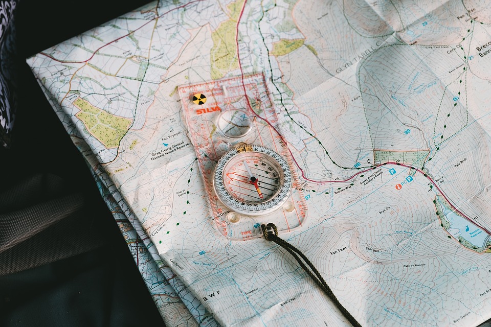
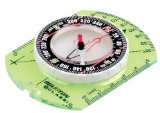
To determine the direction, or bearing, from one point to another, you need a compass as well as a map.
Most compasses are marked with the four cardinal points—north, east, south, and west—but some are
marked additionally with the number of degrees in a circle (360: north is 0 or 360, east is 90, south is
180, and west is 270). Both kinds are easy to use with a little practice. The illustrations on the reverse
side show how to read direction on the map.
 |
One thing to remember is that a compass does not really point to true north, except by coincidence in
some areas. The compass needle is attracted by magnetic force, which varies in different parts of the
world and is constantly changing. When you read north on a compass, you’re really reading the direction
of the magnetic north pole. A diagram in the map margin will show the difference (declination) at the
center of the map between compass north (magnetic north indicated by the MN symbol) and true north
(polar north indicated by the “star” symbol). This diagram also provides the declination between true
north and the orientation of the Universal Transverse Mercator (UTM) grid north (indicated by the GN
symbol). The declination diagram is only representational, and true values of the angles of declination
should be taken from the numbers provided rather than from the directional lines.
 |
Because the magnetic declination is computed at the time the map is made, and because the position of magnetic north isconstantly changing, the declination factor provided on any given map may not be current. To obtain current and historical magnetic declination information for any place in the United States, contact:
National Geomagnetic Information Center
Phone: 303-273-8486
E-mail: jcaldwell@usgs.gov
Web site: geomag.usgs.gov
or
National Geophysical Data Center
Phone: 303-497-6826
E-mail: info@ngdc.noaa.gov
Web site: www.ngdc.noaa.gov
Taking a Compass Bearing From A Map:
Draw a straight line on the map passing through your location and your destination and extending across any one of the map borders.
- Center the compass where your drawn line intersects the map border, align the compass axis N-S or E-W with the border line, and read on the compass circle the true bearing of your drawn line. Be careful to get the bearing in the correct sense because a straight line will have two values 180° apart. Remember north is 0, east is 90, and so on.
- To use this bearing, you must compensate for magnetic declination. If the MN arrow on the map magnetic declination diagram is to the right of the true north line, subtract the MN value. If the arrow is to the left of the line, add the value. Then, standing on your location on the ground, set the compass so that “zero degrees or North” aligns with the magnetic north needle, read the magnetic bearing that you have determined by this procedure, and head off in the direction of this bearing to reach your destination.
- To use this bearing, you must compensate for magnetic declination. If the MN arrow on the map magnetic declination diagram is to the right of the true north line, subtract the MN value. If the arrow is to the left of the line, add the value. Then, standing on your location on the ground, set the compass so that “zero degrees or North” aligns with the magnetic north needle, read the magnetic bearing that you have determined by this procedure, and head off in the direction of this bearing to reach your destination.

A Word of Caution
Compass readings are also affected by the presence of iron and steel objects. Be sure to look out for—and stay away from—pocket knives, belt buckles, railroad tracks, trucks, electrical lines, and so forth when using a compass in the field.
Additional Research:
   |
Leave a Reply